Description
Measure Pro
What it is:
The measure pro is a Panel Pro accessory that provides for reverse engineering instrument panels. It exports the measurements as a DXF CAD drawing for final editing
What it does.
The measure pro measures individual elements such as lines, circles, and curves and saves them as a dxf file for editing in your CAD program. It is a coordinate measuring device, not a scanner or a tracer. Some panels can be measured with hand measuring tools. The curves that are a part of most aircraft panels are very difficult to measure by hand, yet they are a snap for the Measure Pro. The panel perimeter is the primary focus of the Measure Pro, but mounting holes and instrument holes and other panel features can be measured as well.
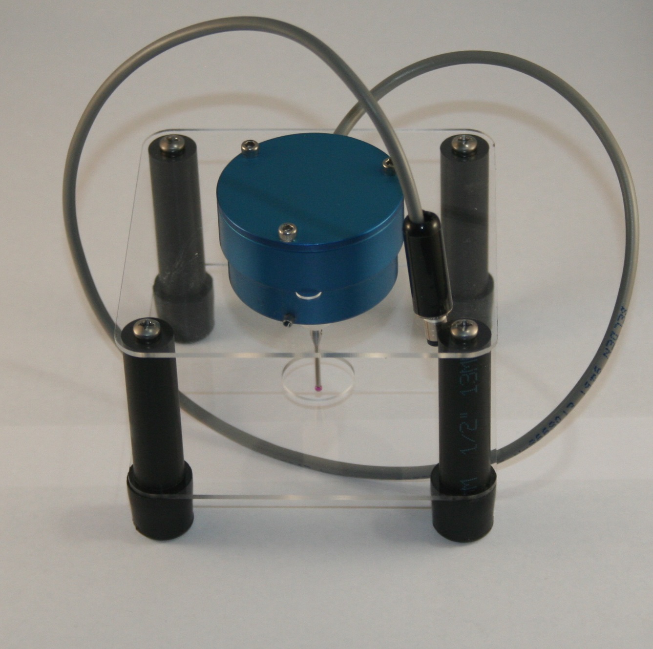
The system consists of:
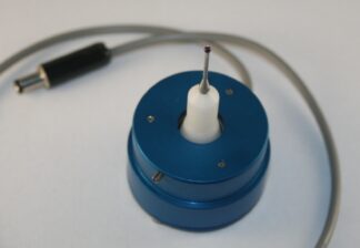
- MP2 Touch Probe. The touch probe is essentially a switch that opens when the 20mm long by 2mm diameter ruby probe tip makes contact with a edge or surface. It triggers +/- X axis, +/- Y axis, – Z axis.
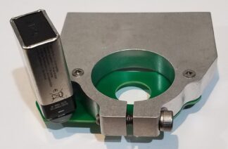
- Probe stand to protect the probe when not in use
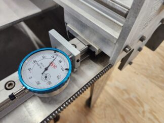
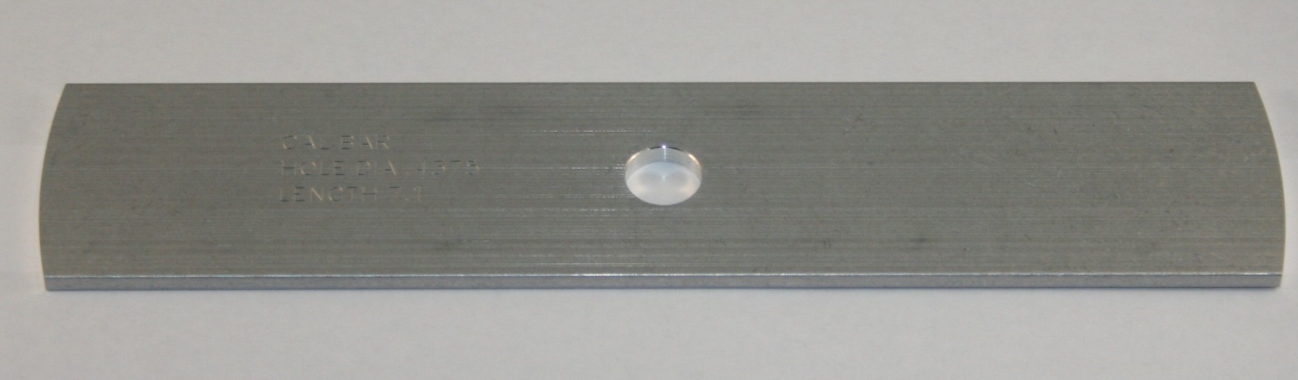
- Calibration bar to set the exact travel required to open the switch.
- The software is part of the AvCAM software included with the Panel Pro 5925a
Operation:
The software utilizes the keyboard key pad for rough x/y movement. For instance if the 6 key is pressed, the x axis will move right until the 5 key is pressed. Most of the measurement tools (software routines with an icon on the tool bar) rely on the user moving the probe into a rough position and then clicking a tool (line, circle, square, ATI, etc.) to measure that feature.
The panel is clamped to the mount rails, squaring as good as you can, but minor out of square can be corrected in later CAD editing.
The software is configured to measure:
Calibration. The system includes a calibration bar. A calibration routine is run in AvCAM and stored for subsequent operation.
Origin (0,0 point) of a panel, usually in the lower left corner, however any x edge may be used as a 0 reference. Any y edge may be used as a Y reference. In addition the center of a hole can be used as a 0,0 point. The origin is the first task after clamping a panel into place. There is a tool to locate the lower left corner.
Lines. Whenever straight lines are encountered, on a panel, measure them as a straight line.
Circles. The circle tools measures round holes. It includes routines to measure knob cutouts.
Arcs. The measure arc tool measures inside arcs and outside corners.
Curves. Used to measure primarily the curved portion of a panel.
ATI (8 sided) cutouts. Handles rectangular (half ATI) as well as symmetrical ATI shaped holes.
Square or rectangular cutouts. Position the probe within the cutout, click the square tool, click proceed. The height and width are recorded as lines.
When measurements are complete, save the dxf file and open it in your CAD. The entities are then edited to extended lines to their intersections, the entire panel can be rotated to correct any minor out of square condition.
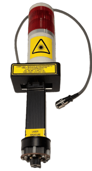
Note: The connectors used have changed over the years.
Current production Panel Pros sn 2036, and 2080 and subsequent use a 10mm 3 pin connector that is also used for laser control.
Serial number 2035, and 2075 to 2079 used a 8mm connector, but we found that the pins were just to small and hard to work with, hence the change to 10mm
Panel Pros earlier than sn 2075, other than specific serial number that have been modified, have a 5.5mm power connector. We would be happy to include the Panel Pro side 3 pin, 10mm connector if requested with the order of the measure Pro.